Today I received and modified iRig Pre ($28) and decided to test it together with RØDE NTG1 ($200) against Takstar SGC-598 ($30). Now, this is not entirely fair comparison if only because the latter should be always camera-mounted while the former can be mounted on a boom.
Nevertheless, give it a listen...
Both mics were sitting about 2 feet from my mouth. Recording was done into Panasonic Lumix G7 with audio sensitivity at its lowest: -12dB. In post I normalized audio and reduced audio channel level by 6dB. No compression or equalization was added. During normalization a gain of 9.2dB was applied to a clip with iRig Pre and a gain of 11.8dB was applied to a clip with Takstar. But the result is a wash in my opinion. Charming! And yes, this is not a fair comparison. But still....
Showing posts with label DIY. Show all posts
Showing posts with label DIY. Show all posts
October 1, 2015

July 5, 2015
Closing Bescor MP-101 Head
This is a follow up to the post where I opened up the Bescor PT head with intent of modifying it for operation with an external DIY controller. And here is the development of this effort in pictures!
I used the components: RJ45 breakout board and double-sided prototype PCB to replace the board electronics. In short, I just connected PAN and TILT motors (see the referenced post on how to identify those) to RJ45 pins 4/5 and 3/6. With a little encouragement from Mr.Dremmel the RJ45 connector is now protruding through the faceplate.
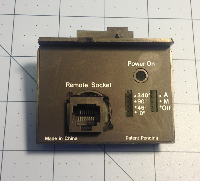
I used the components: RJ45 breakout board and double-sided prototype PCB to replace the board electronics. In short, I just connected PAN and TILT motors (see the referenced post on how to identify those) to RJ45 pins 4/5 and 3/6. With a little encouragement from Mr.Dremmel the RJ45 connector is now protruding through the faceplate.

April 22, 2015
Opening up Bescor MP-101 Head
MP-101 Pan/Tilt Head patent makes for an interesting read. Schematics in the patent depicts two H-bridges built from bipolar transistors. And RF500T motors! Are these Mabuchi RF-500TB? Looks about right. I now seriously think about opening the head and see whether I can discard all the electronics except the motors and have them wired to an existing DIN7 connector. So that I could drive them both using a single TB6612FNG driver controlled by Arduino. Hope to get more predictable results - love simplicity.
So, here is a perfectly working MP-101 head which I am about to disembowel...
 After removing 6 screws you gain access to the electronics compartment.

The very first thing I noticed are those two ICs which look like LB1930 motor drivers. This is fantastic because I now know which wires lead to the motors. It appears that yellow/orange wires lead to tilt motor and green/blue to pan motor. Should I power the head up and see what voltage is used? Never bothered to do that!
 Here is a closer view with motor wires already unsoldered.
Few more screws and the PCB is released. I can see ST LM317T voltage regulator.
 And the rest is just discreet elements. Now, should I do something about those 45°, 90° and 340° end-switches? Well, I tried. But failed.
 First note that there are no wires leading to +60 and +30 contacts. Here are my notes on endswitch wire colors (note that in the photo colors are shifted because of the blue microscope light):
+60 - n/a
+90 - bluish-white
+30 - n/a
+0 - yellow
-0 - orange
-30 - green
-60 - brown ?
-90 - red
All these are neatly routed through a white tube:

Not only the +60 and +30 wires are missing, but I failed to discover how endswitches work. It does look like my Bescor head was tampered - note other contacts missing - there are soldered points with no wires coming. Despite being frustrated with time lost I do not mind it too much - I have now dirrect access to pan/tilt motors. And after selling the remote with cable for $20 my cost is just $50 - I do not think I could remotely approach it with a DIY solution.
So my plan of action is to expose motors contacts via an RJ45 jack and to use regular CAT3 cable to connect the head to the controller! Piece of cake!
So, here is a perfectly working MP-101 head which I am about to disembowel...


The very first thing I noticed are those two ICs which look like LB1930 motor drivers. This is fantastic because I now know which wires lead to the motors. It appears that yellow/orange wires lead to tilt motor and green/blue to pan motor. Should I power the head up and see what voltage is used? Never bothered to do that!

Few more screws and the PCB is released. I can see ST LM317T voltage regulator.


+60 - n/a
+90 - bluish-white
+30 - n/a
+0 - yellow
-0 - orange
-30 - green
-60 - brown ?
-90 - red
All these are neatly routed through a white tube:

Not only the +60 and +30 wires are missing, but I failed to discover how endswitches work. It does look like my Bescor head was tampered - note other contacts missing - there are soldered points with no wires coming. Despite being frustrated with time lost I do not mind it too much - I have now dirrect access to pan/tilt motors. And after selling the remote with cable for $20 my cost is just $50 - I do not think I could remotely approach it with a DIY solution.
So my plan of action is to expose motors contacts via an RJ45 jack and to use regular CAT3 cable to connect the head to the controller! Piece of cake!
April 21, 2015
Automated Video Slider with Pan/Tilt Head - User Interface Demo
Here is a short demonstration of the user interface. See previous posts for requirements and hardware details.
April 12, 2015
Automated Video Slider with Pan/Tilt Head - Hardware Design
In my approach to hardware design I will rely on the affordable off-the-shelf components. Some of those components (slider or head) I already own.
Disclaimer 1: I am neither electrical nor mechanical engineer and I learn as I go. And I love it! I make mistakes and some of my statements could be wrong. Feel free to correct me!
Disclaimer 2: This is a work in progress. I think it should work. But it might be proven to be otherwise.
Parts:
Parts:
Parts:
That's it folks!
Disclaimer 1: I am neither electrical nor mechanical engineer and I learn as I go. And I love it! I make mistakes and some of my statements could be wrong. Feel free to correct me!
Disclaimer 2: This is a work in progress. I think it should work. But it might be proven to be otherwise.
Pan/Tilt Head
Instead of building a pant/tilt head from scratch (which is totally an option, given that I do not need tilt that much! well, maybe later), I will use Bescor MP-101. It is almost affordable (I've got a used one for $80), adequately silent, and can be controlled externally, using Arduino's PWM outputs. The head can be powered by 4xAA batteries, but external power connector is also available. I intend to use the latter.Parts:
- Connect head to the controller using 7-pin DIN cable.
- Power connector?? 5.5mm x 2.1mm?
- Chocolate Factory Pan Tilt USB Hack
- Bescor MP-101 Hack
- Bescor MP-101 Wireless Bluetooth Controller
- CamRanger PT Hub
- StackShot and CamRanger
- USB Pan Tilt Controller with Sony LANC (S-Link) interface
Slider
I already own a cheapo slider from Craigslist, which looks something like this. EDIT: Found it! This is Glide Gear DEV 1000. For now this should do it. I intend to motorize it. I suspect a (cheap) stepper motor will be too jerky and/or loud which is not good for video shooting. Therefore I decided to go with a DC motor. This also means that the position of the carriage will be unknown and its movement speed will be hard(er) to control.Parts:
- 12V DC gearmotor 12RPM. Shaft 4mm
- Motor mount - to be designed.
- GT2 timing belt (6mm wide) with pulleys (20-tooth, 5mm bore).
- 15-tooth, 5mm bore pulley for GT2 timing belt
- TB6612FNG motor driver, datasheet, sample.
- 2x Endstop Switch.
Controller With Display and Keyboard
Parts:- Arduino Mega2560 R3. I decided to go with Mega as opposed to Uno because price difference is negligible and I do not mind extra size. Room for growth is always nice! However if all you want is to control the Bescor head alone, Arduino Uno should suffice.
- Proto Shield. I plan to use this space for slider motor driver. Maybe other parts.
- I strongly believe in the need for appliances to have GUI. This seem like a no-brainier: Keypad LCD 1602 shield. I wish the keys were arranged better and the reset button was less prominent. Alternatively maybe 20x4 LCD display paired with Nunchuck with WiiChuck adapter would be a better option? For now I will stick with the 16x2 LCD/keypad shield and will just rip the reset button and the power LED - it is way too distracting for my comfort.
- Connect to WiFi via ESP8266. For now let's just leave it at that.
Power
I need 12V to drive slider motor - adjust the voltage to make sure sliding is slow enough. 6V to drive the Bescor PT head - adjust the voltage to make sure the panning is slow enough. 7V to drive Arduino and 3.3V to drive WiFi board. I think 12V, 5A DC should be more than adequate and 5.5mm x 2.5mm power connector will do the job. This remains to be proven though.Parts:
- 12V 5A AC power supply connected to controller via
- 5.5mm X 2.5mm DC power supply socket.
- For powering the PT head or even Arduino I might use this DC-DC step-down module.
- Battery power. I can go with a cheap 12V battery pack. Alternatively Sony NP-Fxxx compatible batteries are readily available and, most importantly, I already own a few to power LED lights. In this case I will also need a plate and DC-DC voltage booster.
That's it folks!
Automated Video Slider with Pan/Tilt Head - Requirements
Being a one-man shop I often wish I had an extra pair of hands to control the second camera. Usually I set such a camera with a wide-angle lens trained at the event audience. To add life into the footage some panning and sliding are highly desirable. I am thinking most of the time this task can be fully automated!
Let's call this automated slider with pan/tilt (possibly zoom) head a camera control system. Or the system for short.
Let's call this automated slider with pan/tilt (possibly zoom) head a camera control system. Or the system for short.
High Level Requirements
- Once setup, the system should be capable of operating fully autonomously, with no operator involvement for at least 2 hours.
- Operator will be able to program the system. The program/script will reside in a separate file which can loaded/saved or created on the fly.
- The script will contain instructions like these:
- Rest 5 secs
- Pan left 20°
- Rest 15 secs
- Slowly pan left and slide left for 5 secs
- Camera control script requirements will be spelled out separately. Including:
- Operations supported include pan/tilt/slide/zoom/rest.
- It should be possible to run operations in parallel or in sequence or in a loop.
- Operation arguments will be in time units or angle or distance units.
- Operation with no argument may have qualifier, e.g. fast or slowly.
- Exceptions such as a slider reaching a limit or boundary should be supported.
- System should be scalable in terms of its capabilities. E.g. it should be possible to use automated slider without automated Pan/Tilt/Zoom head. And it should be possible to use the automated PTZ head without the slider. Similarly the script created for a long slider should be usable on a smaller slider.
- System should tolerate power interrupts. Ideally, once the power is restored, system should continue execution of the script where it was interrupted.
- Power supply should be modular, so that both battery and AC power are supported.
Constraints
- System power supply should be modular, so that both battery and AC power are supported.
- System will be built from the readily available of-the-shelf components. Integration level of such components should be as high as possible.
February 28, 2014
DIY: Video Clamp

You take eBay C-clamp ($9), remove the spigot and attach in its place a metal shelf bracket ($6) and add to its tip a small ball head ($6). Done.
I use it to mount audio or video recorder to the light stand. The substantial length of the bracket ensures that the camcorder's flip out screen can be manipulated freely. I also like the clamp's rubberized surfaces being gentle on my equipment. Nice!
December 29, 2013
DIY Floor Light

So I started with a $10 eBay umbrella adapter I already had and went to IKEA to pick the rest components. Click the image on the left for more step-by-step pictures.
I settled for a Rodd table lamp base (a cheaper and shorter version would be better but I never realized it existed!) and an Ollsta shade (you decide which size - I picked a larger one.) I liked how the wire is routed in the Rodd base - it goes out to the side and the switch is at the very top. Thus removing the base and replacing it (somehow) with an umbrella adapter should not interfere with wiring. BTW this shade can be installed with wider opening down OR up. I though it was a nice touch.
So the first step is to remove the cold shoe from the umbrella adapter. This exposed a nice hole. I then went back to Rodd lamp base. The base itself has a tube adapter which I removed. Now I had to figure out how to attach this lamp tube adapter to the umbrella adapter. An M6 bolt which I already had looked like something which can do the trick. A visit to a big box store brought me Irwin Metric Tap and Die Set. I tapped an M6 thread in the umbrella adapter. I cut of half of the lamp tube adapter and I drilled a hole and tapped the same M6 thread there. Then I cut off an M6 bolt head and screwed it both into the umbrella and lamp tube adapters.
And that was it!
December 2, 2012
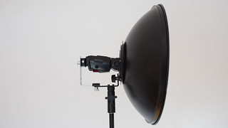
Study in Dishes. New Flash Mount.
March 24, 2011
DIY: Diffusion Panels
This was my first DIY project which still exceeds the rest by its versatility and bang for a buck.
I currently have two frames of about 4'x7' made of 3/4" schedule 40 PVC pipes and joints. I use these to stretch either diffusion/reflection screens made of white rip-stop nylon or a black canvas screen. As I mentioned before, build process is well documented on the Internet. Here is the necessary attribution to Dean Collins' tinker tubes with some BTS videos of this great guy.
This is what my panels look like.
I currently have two frames of about 4'x7' made of 3/4" schedule 40 PVC pipes and joints. I use these to stretch either diffusion/reflection screens made of white rip-stop nylon or a black canvas screen. As I mentioned before, build process is well documented on the Internet. Here is the necessary attribution to Dean Collins' tinker tubes with some BTS videos of this great guy.
This is what my panels look like.
February 27, 2011
DIY: PVC Light Stand
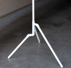
I am pleased with the result. As one might have expected the stand is not rigid (because of the flexibility of the PVC pipe) yet surprisingly stable. Besides, because of the different height of the legs one can put two such stands very close to each other - try that with alternative designs!
February 24, 2011
DIY: Wearable Flash Rig and Diffusion Panels
I just realized that I never properly documented any of my DIY projects - wearable flash rig, diffusion panel or light stand. Consider this in place of a "proper" documentation.
 I use a wearable flash rig to take photos in a bright sun and I built it specifically for Burning Man 2010. It proved to be an awesome solution for fill flash in a bright desert sun. Just put your subjects with their back to the sun, "say I'm soooo cute" and press the shutter. Majority of these photos were taken with this rig - Nikon D90 on-camera flash driving via CLS 2xSB600 flashes being controlled by TTL. Manual control is also an option. The rig is made of 1/2" schedule 40 PVC pipes and joints. It is a great conversation starter but be careful if you decide to wear it in the club - please be gentle to your neighbors in crowded places.
After this post was published I found an even more grandiose approach to a moveable lighting rig: Human Light Suit. Designed for exactly the same purpose, Eric Schwabel's rig can overpower the Burning Man sun! And the catch-light is nothing short of amazing!

After this post was published I found an even more grandiose approach to a moveable lighting rig: Human Light Suit. Designed for exactly the same purpose, Eric Schwabel's rig can overpower the Burning Man sun! And the catch-light is nothing short of amazing!
September 30, 2010
Diffusion Panels
They are awesome! They rule the kingdom of DIY Light Modifiers through their old servant Bang for the Buck. Which still goes strong in my domain.
 They can soften the sun or bare flash. They can be used as a reflection panel for something like this or just put on the ground for this nice cookie-cutter solution (fast forward to about 50% for behind the scene details). It works so well, after trying one I built another. Both are a little more than 4'x7' and are made of 3/4" schedule 40 PVC pipe and rip-stop nylon. Here is the necessary attribution to Dean Collins' tinker tubes with some BTS videos of this great guy. Building process is well documented.
Look at this one flash head-shot - compare results of use of a 43" diffusion umbrella to that of a 4'x7' diffusion panel. The light diffused by a large panel is soft and enveloping.
The (only) bad news is that a more powerful light source (or sources!) are desired. Need to check my Amazon rewards balance!
What works:
Look at this one flash head-shot - compare results of use of a 43" diffusion umbrella to that of a 4'x7' diffusion panel. The light diffused by a large panel is soft and enveloping.
The (only) bad news is that a more powerful light source (or sources!) are desired. Need to check my Amazon rewards balance!
What works:
- Large (4'x7') diffusion panel made from PVC pipes and rip-stop nylon offers good quality (both diffused and reflected) light for about $25 in materials. It is still relatively portable - can be packed in seconds into a 4'x8" cylinder.
- Ball bungee cords work great to keep the disassembled frame pieces together. They can also be used to attach one such frame to another.
- I am starting to run into limitations of 2x SB-600 flashes. For a high key setup I need at least 3, better 4. But this has (almost) nothing to do with the subject.
Subscribe to:
Posts (Atom)